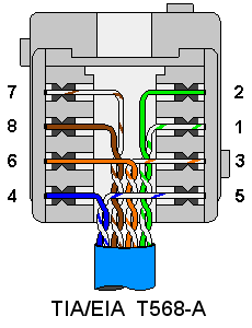
Each part should be set and connected with different parts in specific manner. Assortment of cat 5 wiring diagram wall jack.
 Cat5 Telephone Wiring Junction Box Diagram Daily Update
 Variety of cat 5e wiring diagram wall jack.

Cat5 phone wire diagram. A wiring diagram is a simplified traditional photographic depiction of an electrical circuit. The kind of wire shown above has recently become obsolete. In which case start with the blue pairs and use the orange pairs for the second line.
Cat5 phone line wiring diagram cat5 phone line wiring diagram every electrical structure is made up of various different pieces. The four colors are in order blue orange green and brown. Click to find view and print for your reference.
Regular phone cable consists of two untwisted pairs each with wires of a different solid color the. Variety of cat 5 wiring diagram pdf. Cat5 telephone jack wiring diagram collections of cat5e socket wiring diagram cat 5 for telephone wire phone.
Thus when refering to the second pair of wires it is the orange pair. During the second half of the 20th century is of the following kind. Cat 5 wall jack wiring diagram sample.
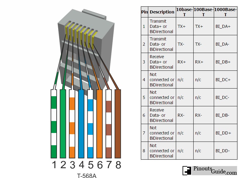
Cat 5 wall jack wiring diagram collection. Most phone wire installed in the us. To remember the rj45 wiring order we created tools that make it easy to memorize.
Nowadays cat5 cable is commonly used instead of station wire for telephony. It shows the components of the circuit as simplified shapes and also the power as well as signal connections between the devices. It reveals the elements of the circuit as simplified forms as well as the power and signal connections in between the gadgets.
A wiring diagram is a simplified conventional pictorial depiction of an electrical circuit. Since 100mbs ethernet only uses 4 of the 8 wires normally found in an ethernet cable even old 4 wire cat 3 telephone cabling can be wired for. A wiring diagram is a simplified standard photographic representation of an electrical circuit.
In most residential phone wiring the cable contains four individual wires. Otherwise the arrangement will not function as it should be. Converting home telephone wiring to ethernet.
The four wire pairs in a cat 5 cable are distinguished by the color of their insulation. Wiring diagram for cat5 to phone jack further telephone jack wiring. Some premade phone cables only have the center two wires.
It shows the components of the circuit as streamlined forms and also the power as well as signal connections between the tools. For all new telephone wiring projects you should use cat 5 cable. These cables will be absolutely useless for two line devices.
The complete ethernet pinout cable wiring reference with wiring step by step guide. Telephone cabling using cat5 or utp. Rj45 pinout diagram for standard t568b t568a and crossover cable are shown here.
 74d Home Phone Wiring Diagram Using Cat5 Cable Epanel
  Doing Your Own Telephone Wiring
  Cat5 Phone Wiring Diagram Wiring Diagram
  Cat5 Phone Wiring Diagram Wiring Diagram
  Cat5 Voip Wiring Wiring Diagram 500
  Telephone Wall Jack Wiring Cat 5 Wiring Diagram Options
  Rj11 Phone Wiring Wiring Diagram Rows
  Cat Cable Diagram Wiring Diagram 500
  Rj11 Wiring Diagram Phone Wiring Library